Technical Aspects
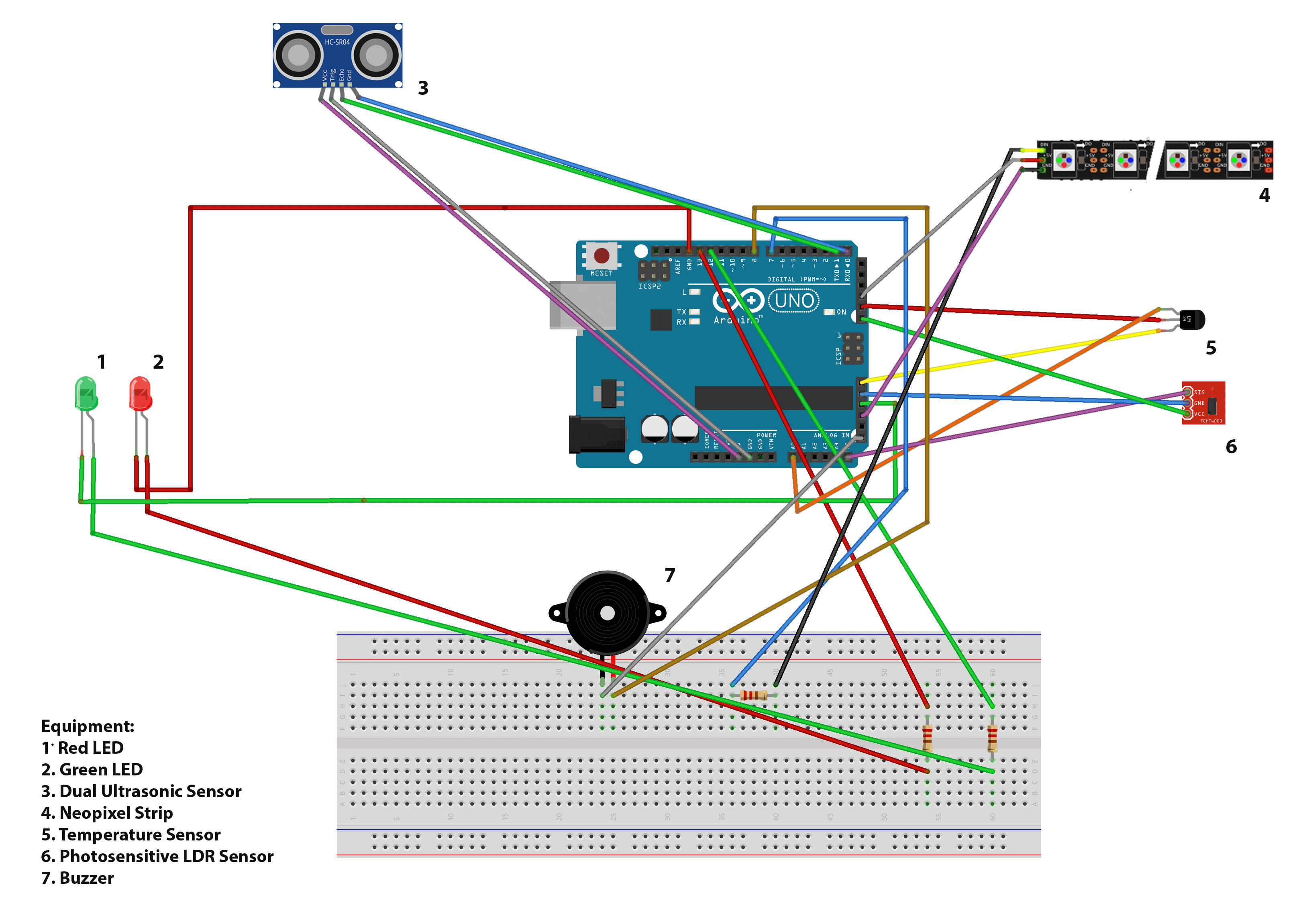
Emily is controlled using an Arduino, which is an electronic prototyping platform that can read inputs and produce outputs through the software and hardware. I have used a range of equipment to perform some of the features that Emily proposes. The different equipment is able to be incorporated into the one programmable circuit board (or microcontroller) and uploaded file. The sensors and other equipment plug into the different pins with the use of a breadboard. Below is a circuit diagram of Emily with an explanation of each function to follow.
Monitoring the Light Usage
The first function that is programmed is the monitoring of the light levels in the user’s room. The values produced by the photosensitive LDR sensor are read and printed into the program. If the light level is less than a certain value, that suggests the lights are off, dimmed, or natural light is occurring. A green light appears to represent the appropriate use of energy. If the lights are above a certain level, the vibrations from the ultrasonic sensor are read. If the distance of the movement is less than a metre, the light will also turn green as this indicates there is someone in the room and thus the lights are on for a reason. If the movement is further away or not detected at all, the red light will turn on and the buzzer will alarm. The user will be able to either visually or audibly recognise their misuse and can choose to change their actions to make Emily happy again. You can view the source code for this function below.

Monitoring the Air Conditioner/Heater Temperature
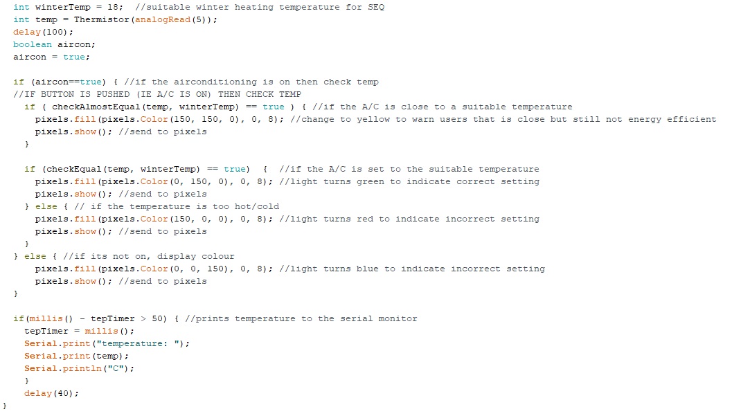
The ideal temperature that the system should be set at is set to 18C, which was determined through research. The program then reads the values from the temperature sensor, decodes it using the Thermistor method, and then assigned to a variable. Next the air conditioning’s status is read (this value is currently simulated through a simple true or false within the code). If it is on, the values of both the energy-efficient temperature and current room temperature are compared. If they are almost equal (within 2.5 degrees), the LEDs on the neopixel strip will display yellow, using the Adafruit Neopixel Library. This indicates to the user that they should be weary of their current air conditioning temperature and are given the opportunity to improve their actions. If the temperatures are found to be equal (within 1 degree), the system will turn the neopixels green indicating an appropriate, energy-efficient temperature in the room. If the two temperature values are not equal or almost equal, the neopixel strip will appear red to alarm the user of the difference in temperature and the inefficient energy use. Whilst the user can immediately change the temperature setting on the air conditioner, the room may take some time before the actual temperature changes. However, the user will be able to see when their room temperature is nearing an appropriate level through the neopixel lights. If the air conditioner is found to not be on, the neopixel strip will display a blue temperature and the user is embracing the natural temperature and thus being energy-efficient so there is no need to cause alarm. Below you can view the source code for this function.
Physical Form
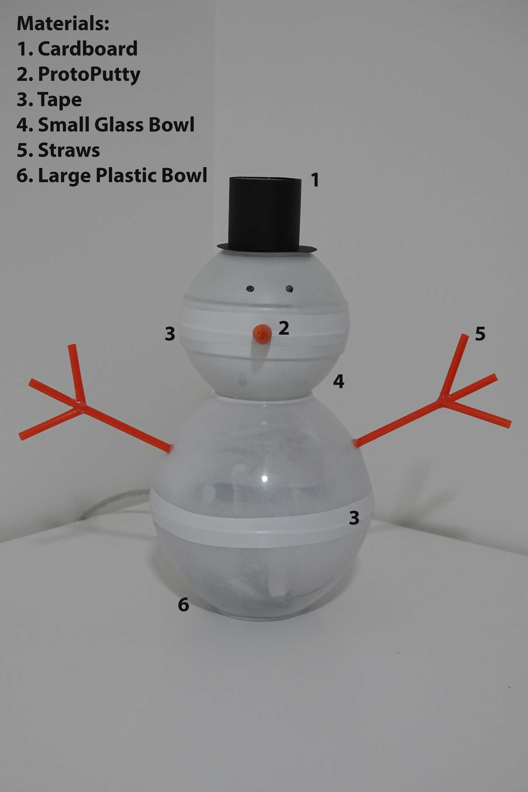 Emily’s body is made of four bowls: two large plastic bowls and two small glass bowls. Both sets of bowls are placed together to create two spheres, in which the smaller bowls are glued to the top of the larger set. They are held together by tape to allow access for the Arduino contained within the larger bowls. The bowls have a light coat of a white matt spray paint to allow for transparency but still give enough colour to distinguish the sculpture. The top hat is placed on the head of the snowman and is made from black cardboard. Individual pieces were cut out and glued together to create a hat. The nose was made using ProtoPutty and forced into a cone shape. The arms were created using straws that were cut and carefully pieced together to create the fingers and an arm.
The Arduino equipment is held inside the body of Emily with some equipment contained outside. The LED lights are enclosed within the head of the body to allow for the user to distinguish between the LED lights (representing the light sensor) and the neopixel strip (representing the temperature sensor). The ultrasonic sensor is also kept within the head to allow for higher accuracy whilst still being hidden. The temperature sensor and photosensitive LDR sensor are kept outside of the structure so that the light and heat inside the body does not alter the results of the sensors. The parts are held to the body with tape to minimise the sight of these from the front. Below you can view an annotated photo of Emily and the materials used to create her.