Technical & Physical
MathDice
Technical & Physical
MathDice
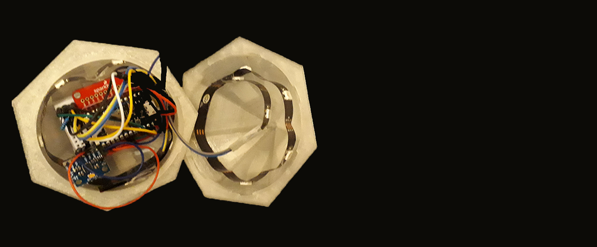
There were various materials, sensors and equipment used to create and build the MathDice. The physical form was made out of clear PLA and 3D printed to have fourteen sides, as thirteen were needed to allow children to roll numbers from zero to twelve, this enabled them to learn and practice the times tables. For practical reasons, the two halves of the dice can be locked and screwed open or closed to add or remove sensors from inside the dice. Clear PLA was used to allow the light from neo-pixel strips to show without the distortion of another colour. The size of the dice had to be bigger than normal die to allow the sensors to fit inside and close.


There were three sensors used for the prototype, the particle photon with battery shield and battery, two 8 RGB neo-pixel strips and an MPU6050
accelerometer and gyroscope. The particle photon was used to power the neo-pixel strips and MPU6050 as well as send data wirelessly to the cloud.
This enabled the measurements from MPU6050 to determine which side was facing upwards. From the data, the RGB light on the neo-pixel strips would
be coded to light up a certain colour if the number they are representing is rolled. The battery shield was used to protect the particle photon
when powered with the battery and connected to the other sensors on the breadboard. Two neo-pixel strips were used as there are two halves to the
dice. The two strips were positioned in a circular shape to allow the majority of the sides to have a light on the inside. For the first strip,
seven out of 8 RGB lights were needed as there were seven sides and six out of eight for the bottom half.


How the circuit was wired was to connect the neo-pixel 5V pin to Vin, Din to a resistor, which connected to D6 and neo-pixel GND to the photon GND.
The only difference for the second strip is Din is connected straight to pin D5 on the particle photon. The last sensor used was MPU6050 which
provided the gyroscope x values and accelerometer x and z values to determine the side rolled. The sensor was not completely accurate; thus, a
range of values was used for each side. When the sensor was used for the first time it was found that there was a lack of connection and thus, it
had to be soldered and then connected to the particle photon via the breadboard. The circuit for this includes a pin VCC connected to Vin on the
particle photon, GND connected to GND, SCL to D1 and SDA to D0. Other resources were a small breadboard to connect all the sensors via wires.

